Part 1 - BlocksCAD 101 - Making 3D Models with Code Blocks
Part 2 - BlocksCAD 102 - Coding a #3D Box that Grows
In this part 3, you'll see how using parameters to make a box, makes it simple to make a fitted box top. With this method, a simple change in ONE value in your code will change the dimensions of the box AND the top!
Design Goals
No matter how you create your 3D Models, you should always think first about your design goals. For this box plus matching box top project, we want the box top to be flush with the outside of the box, and we want it to have a protrusion on the inside to let it sit perfectly in place over the opening of the hollow box. In essence, we want a rectangle top, with a smaller rectangle protruding from the bottom which matches the inner dimensions of the hollow top of the box.
Using Values To Create Objects
 In Part 2, we created a box of a specific size using a variable we called "block-size". We also declared that we wanted the thickness of the walls of that hollow box to be determined using the variable we called "wall-thick". Now that we're looking to make a fitted top for that box, those dimensions will come in handy.
Start With Basic Shapes
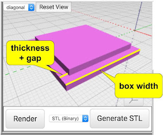
Let's think about our box top as two rectangles - one which is the same width and length as outside of the box itself, one one smaller rectangle sitting on top of the first, centered, which matches the smaller dimensions of the hollow part of the box. We're printing this box top upside down, which is why the smaller rectangle is on top.
The thickness of the box top (the height when printing - also known as the z-axis value) can match the thickness of the walls of the box - so that will use the "wall-thick" variable value. The thickness (depth) of the protruding, smaller rectangle can also use that thickness value. Simple! So the first rectangle is created using the following CUBE block.
The smaller rectangle is slightly trickier. It's size is basically meant to be the same size as the INNER dimensions of the hollow box, so that would be calculated as the outer dimension, minus the thickness of the walls. Since there is a wall on each side of the x dimension and y dimension, that means we have to subtract TWO TIMES the wall thickness from the block size to get the inner dimension of the smaller rectangle. Let's create a new variable to calculate that size and call it "sm-block". That variable, and the subsequent creation of the smaller block is shown below:
Making The Top Fit Better
If you've ever printed 3D objects that are meant to fit together, you know that a 10mm part will NOT fit into a 10mm hole. There is always the need for additional gap between parts to make them fit. The value of this "coding objects" method is that we can code that gap - and adjust it for different materials or different printers. On my Polar3D printer, I know that I usually need about 0.35mm gap on either side for a loose fit - which is about 0.7mm total on each dimension (I made it 0.75mm).
 Now in the X and Y dimensions of that smaller rectangle, I subtract the value of "gap-mm" to allow for the proper fit. If I find the fit to be too tight, I simply increase that value to give a bigger gap.
Put The Shapes Together
Now that we have the two basic shapes, we can put them together to construct the box top.The most powerful code blocks in BlocksCAD are in the "SET OPS" group (Set Operations). For this object, we need to combine the two distinct rectangles using the "UNION" block. This is a pretty common operation, which combines two shapes into one.
Notice that before combining the second shape (the smaller rectangle) with the first, we need to shift it up a bit so that it sits on top of the first shape. That's where the "TRANSLATE" code block comes in. We shift the position on the Z-Axis by the thickness of the first rectangle.
The code shown above s the complete code block which makes the Box Top - but notice that it relies on the variables from the prior examples where we made the box itself. Specifically, the block-size and wall-thick variables.
 |
| The finished product in two sizes - 10mm and 30mm |
NOTE: this is the third in a 3-part series on making models with BlocksCAD code.
Part-1 - Making 3D Models with Code Blocks (aka Intro to BlocksCAD)
Part 2 - BlocksCAD 102 - Coding a #3D Box that Grows


No comments:
Post a Comment